FEA Analysis of Pressure Vessels with Simcenter 3D
- Alvaro Filho

- 3 days ago
- 4 min read

Pressure vessels are important components in several industries, such as petrochemicals, pharmaceuticals, food, metallurgy, etc. Designed to store fluids under pressure, these devices must withstand high temperatures and pressures without compromising safety. Any failure can result in serious risks, such as leaks, explosions or contamination of the environment. Below are some of their main functions:
Storing gases under pressure, so that they can have a greater weight in a relatively small volume;
Intermediate accumulation of gases and liquids, in systems where this function is necessary, between the stages of the same process or even between different processes;
Processing of gases and liquids, when the transformation process requires that the conditions be under pressure.
In addition, pressure vessels often operate under pressurization and depressurization cycles, which makes them susceptible to structural fatigue. Therefore, standards such as ASME BPVC Section VIII and API 579-1/ASME FFS-1 establish guidelines for their design, manufacturing and numerical analysis, to protect against failures due to continuous loading.
Therefore, the application of finite element analysis (FEA) is essential to ensure the structural integrity of this equipment before manufacturing and during its operation.
FEA modeling
Finite element analysis allows simulating the behavior of a pressure vessel under different operating conditions. For this study, we considered a horizontal cylindrical vessel subjected to internal pressure and temperature.
The analysis process followed the following steps:
Definition of the CAD model
The pressure vessel was modeled in SIEMENS Solid Edge CAD software.

Image 1: Solid model

Image 2: Main dimensions
Determination of Material Properties
The material chosen was ASTM-A516 Grade 70 steel, widely used in the manufacture of pressure vessels due to its mechanical strength and toughness.
Yield Strength | 260 MPa |
Rupture Strength | 485 MPa |
Tangential Modulus | 1460 MPa |
Young's Modulus | 200 GPa |
Poisson's Ratio | 0,3 |
Density | 7,80 g/cm³ |
Coefficient of Thermal Expansion | 12x10-6 1/ºC |
ASTM-516-70 Properties Table
Transformation into a shell (surface) model
After dimensioning it in Solid Edge, we imported it into Simcenter 3D, SIEMENS' finite element analysis (FEA) software, to transform it into a shell model to optimize the analysis and simplify the geometry. Due to the high thickness of the bases, they were kept as solid elements.
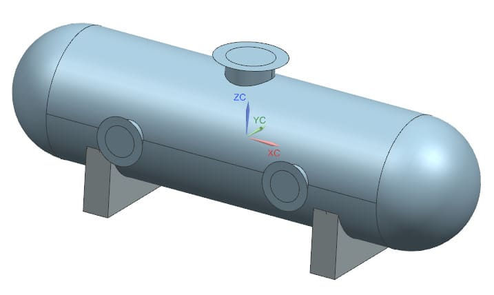
Image 3: Shell model
Generation of the Mesh
Use of 2D meshes (CQUAD4) on the “surfaces” with low refinement due to the simple model and 3D mesh (CTETRA4) on the bases.
In the 2D meshes, we specify the thicknesses of the components in the manifold where the meshes are located, so a manifold is required for each thickness.

Image 4: Representation of the meshes
Application of boundary conditions and restrictions
Fully fixed restriction on the left base and the one on the right fixed only for translation in Z.
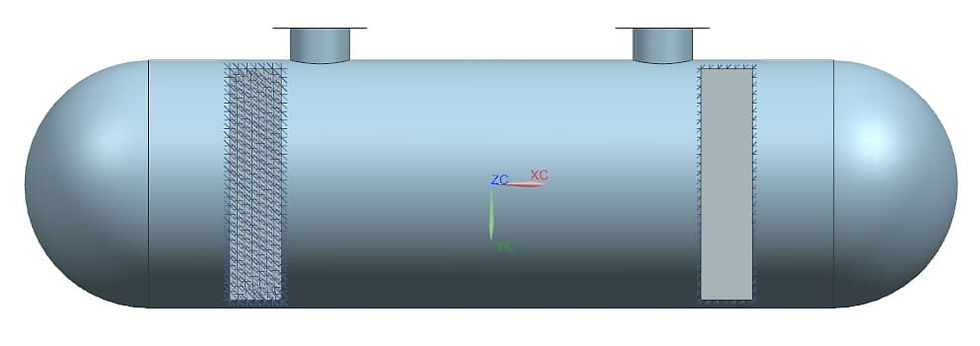
Image 5: Base restrictions: (a) fixed left and; (b) fixed right translation in Z
Internal pressure
Pressure of 2 bar on walls and pipes.

Image 6: Representation of pressure
Temperature
The object is at an initial temperature of 20 ºC, with the body going to 100 ºC (image 7) and the base going to 40 ºC (image 8) in the simulation.
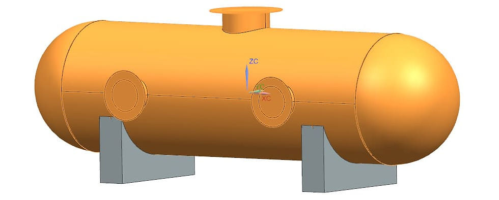
Image 7: Components at 100 ºC

Image 8: Components at 40 ºC
Running the simulation using the NASTRAN solver integrated with Simcenter 3D
Results
The analysis results show that the maximum displacement occurs at the right end of the pressure vessel, reaching approximately 0.78 mm, as shown in image 8. Because it is fixed to the left base, it tends to move to the right, as shown by the simulation behavior. This deformation is relatively small, indicating good structural rigidity for the applied load conditions.


Image 9: Displacement results
The stress results show that the highest stress concentration is occurring at the base, with a peak of 262.80 MPa (image 9) at the junction with the body, which is consistent since it is a region with sharp corners. It can be seen that it is in this region where the stresses exceed the yield limit (260 MPa) of the material, which may indicate a risk of local plasticization.
In the body of the vessel, the maximum stress is 156.58 MPa at the border with the base (image 10), demonstrating that it is within a safe margin of the yield limit.
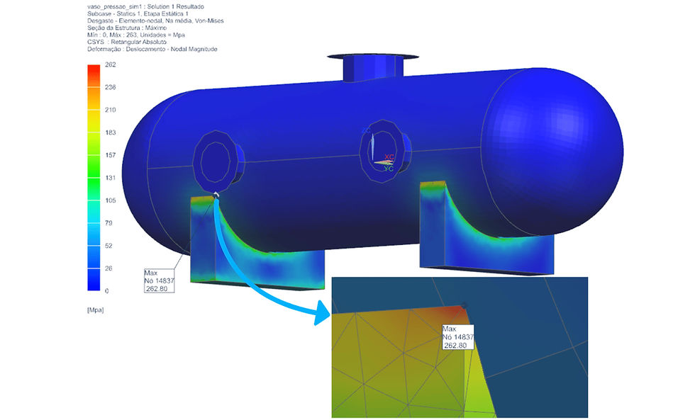
Image 10: Result of tensions
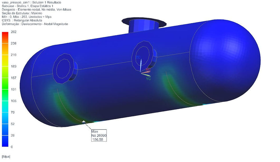
Image 11: Stress peak in the body
Benefits of FEA Analysis for Pressure Vessels
The use of FEA in pressure vessel engineering brings several advantages:
Cost Reduction: Minimizes the need for expensive experimental tests and optimizes the use of materials.
Accuracy in Structural Analysis: Identifies critical points and improves the design before manufacturing.
Increased Safety: Allows for the prediction of structural failures and compliance with strict standards such as ASME BPVC Section VIII and API 579-1/ASME FFS-1.
Design Optimization: Allows for structural adjustments to increase the useful life of the equipment.
Designs based on the ASME BPVC Section VIII Division 2 Part 5 (Design by analysis) code can reduce material costs and equipment weight due to its lower rigor and because it allows for higher allowable stresses, compared to Section VIII Division 1, which is more conservative. ASME BPVC Section VIII Division 2 establishes the following criteria for failure prevention:
Plastic Collapse - Evaluates possible locations where major failures may occur.
Localized Failure - Small regions that exceed the material's resistance limits.
Buckling - Caused by axial compression or vacuum in pressure vessels.
Fatigue Failure - Components subjected to cyclic loading.
All of these requirements and changes during design, such as changes in thickness and materials, can be achieved using Simcenter 3D in a simple way.
With these advantages, FEA analysis becomes an indispensable tool for engineers seeking efficient and safe designs for pressure vessels. Computer simulation not only improves the reliability of projects, but also speeds up validation and certification processes in the industry, with approval from standards such as ASME.
Do you want to ensure the structural integrity of your pressure vessels, save on materials and still comply with strict standards such as ASME BPVC? Schedule a meeting with CAEXPERTS and find out how FEA analysis can increase the safety and efficiency of your projects. We are ready to transform complex challenges into smart and safe solutions!
WhatsApp: +55 (48) 98814-4798
E-mail: contato@caexperts.com.br


留言