Fuel Cell Validation: Case Studies – Part 2 – FEA
- Alvaro Filho
- Aug 16, 2024
- 6 min read

Welcome to part 2 of our special technical blog series on computational simulations in engineering! If you haven’t already checked out part 1 on CFD modeling, we recommend checking it out here for a complete overview of the project. In part 1, we detailed the multiphysics modeling and CFD simulation of a fuel cell using Simcenter STAR-CCM+.
FEA Case Study
In this second part of the series, we will focus on the modeling and structural analysis of a proton exchange membrane fuel cell (PEMFC). Using Solid Edge software for CAD modeling and Simcenter 3D for finite element analysis (FEA), we seek to validate the structural robustness and mechanical resistance of the cell under various operating conditions. Simcenter 3D is a simulation tool that allows the integration of several physics in a single model, as in the case of a PEMFC where there are pressure and temperature fields imported from STAR-CCM+ and also application of bolt tightening.
As a reminder, to validate the CFD model, we used the JRC ZERO∇ CELL (BEDNAREK et al., 2021), chosen for its reliable technical documentation and the availability of experimental data at its source, which is a technical report from the Joint Research Centre (JRC) (Figure 1). The JRC is the science and knowledge service of the European Commission, responsible for providing scientific and technical support to European Union policymaking by developing and providing methods, models, and data.
Figure 1 – Excerpt from the Joint Research Centre technical report on the JRC ZERO∇CELL

Source: Adapted from BEDNAREK et al. (2021)
The availability of technical drawings of the cell geometry (Figure 2), the materials used and some conditions of use also favored its choice.
Figure 2 – Technical drawing of the JRC ZERO∇CELL assembly, together with the description of the cell parts
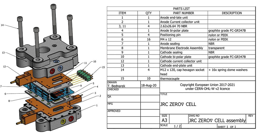
Source: Adapted from BEDNAREK (2021)
1 Modeling
This topic will explain and discuss the most relevant points of FEA modeling. The simulation was developed based on the data and conditions provided in the article. In summary, the steps of the FEA study were as follows:
Generation of the complete geometry of the problem;
Adaptation of geometry for FEA analysis;
Definition of boundary conditions;
Generation of the computational mesh (division of bodies into small elements);
Execution of the model and verification of results;
If the results are not consistent, steps two, three and four are reviewed;
If the results are consistent, they are then processed.
Next, the modeling will be divided into topics and further detailed.
1.1 Geometry
The PEMFC geometry (Figure 3) was developed based on the technical drawings of BEDNAREK (2021), referring to JRC ZERO∇CELL. For the FEA analysis, it was necessary to model all the parts and geometries provided by the document, since all of them will have an impact on the cell's stress and sealing results. However, small details were removed, such as aesthetic or assembly chamfers and very small gas flow channels, aiming at a simplification of the mesh.
Figure 3 – Geometry (Isometric View)

Figure 4 – Geometry (Side View)

1.2 Boundary Conditions
The boundary conditions in a structural simulation are definitions that specify the forces acting on the system and the way in which that system is fixed in space. In addition, it is necessary to choose the materials for each component with their respective mechanical properties – and thermal properties, as in this case.
1.2.1 Restrictions
As restrictions, we chose a fixation condition on all axes of the lower face of the cell, since the article does not specifically mention how the cell was fixed and we are focused on the sealing efficiency of the system, that is, we do not need to worry about the accumulation of tensions on the lower face or problems of excessive restriction of the model. The fixation face is made explicit below.
Figure 5 – Model fixing condition
1.2.2 Materials
The materials used were chosen based on the data provided by the article and using the materials from the standard Simcenter 3D library, applying these to the meshes of their corresponding parts. Below is an image for each material used, showing their respective parts and then their properties.
Figure 6 – Steel Parts
Steel properties:
Density: 7829 kg/m³
Modulus of Elasticity: 206940 MPa
Poisson's ratio: 0.288
Coefficient of Thermal Expansion: 1.128e-05 1/Cº
Figure 7 – AW2024T3 parts

AW2024T3 properties:
Density: 2794 kg/m³
Modulus of Elasticity: 73119 MPa
Poisson's ratio: 0.33
Coefficient of Thermal Expansion: 2.16e-05 1/Cº
Figure 8 – Bronze Pieces

Bronze properties:
Density: 8852 kg/m³
Modulus of Elasticity: 103400 MPa
Poisson's ratio: 0.34
Coefficient of Thermal Expansion: 1.782e-05 1/Cº
Figure 9 – Rubber Parts

Rubber properties:
Density: 1200 kg/m³
Modulus of Elasticity: 900 MPa
Poisson's ratio: 0.4
Coefficient of Thermal Expansion: 0 1/Cº
1.2.3 Efforts
In the structural simulation, we will have two times, the first applying the preload of the 4 bolts and the second applying the temperature and pressure conditions provided by the CFD analysis.
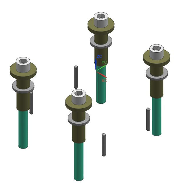
To tighten the bolts, the data provided in the article was used and a strategy was adopted to apply this force properly. In Simcenter 3D, there is a loading called “ Bolt Pre-Load ”, that is, bolt pre-load. In this loading, it is possible to apply a force on a given axis by choosing a face, for example, so that this face will be compressed on the chosen axis. Therefore, the bolt was cut in half transversally and another Simcenter 3D feature was used , called “ Mesh Mating ”. This feature unifies meshes of separate bodies, connecting the nodes so that they become coincident, practically unifying the meshes of the chosen bodies.
Therefore, using “ Mesh Mating ” for each screw cut in half and applying “ Bolt Pre-Load ” to the faces generated by the cut, the screws are tightened from this face given the force applied. Below you can better understand the procedure adopted.
Figure 10 – Cut screw

Figure 11 – “Bolt Pre-Load”

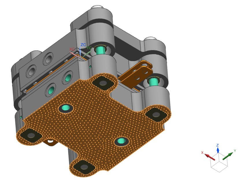
Moving on to the second part of the analysis, the results obtained in the CFD analysis were imported in .csv format, which in Simcenter 3D was transformed into a cloud of tabulated points for both temperature and pressure. Figure 12 below shows the pressure and temperature fields applied to the system. In it, it is possible to see the meshes in which the conditions were applied, the small red arrows indicating the pressure field and the blue region that is under the temperature conditions extracted from the CFD analysis.
Figure 12 – Pressure and temperature fields

2 Results
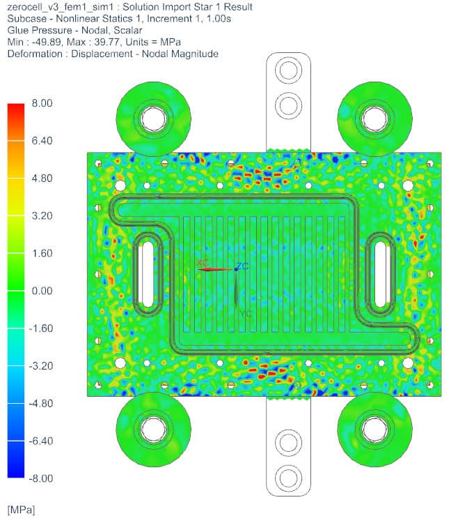
As a result, the contact pressure between the plates around the membrane and the fatigue resistance of the system can be highlighted.
2.1 Contact Pressure
To assess the cell's sealing efficiency, it is necessary to analyze the forces acting to prevent the plates from losing contact. The preloading on the screws and the contacts between the plates were considered. We can evaluate the pressure involved in these contacts and compare them with the results obtained in the article to validate the model.
Figure 13 – Interface contact pressure

Figure 14 – Contact pressure
2.2 Fatigue Resistance
To analyze fatigue resistance, it is necessary to simulate that the load imposed in the static analysis will be applied repeatedly to the system. To do this, we use the “ Durability ” tool in Simcenter 3D. In this analysis, we use the yield strength of each material as a reference to calculate the safety factor. Figure 15 and Figure 16 below show the safety factor of the system, which remained above 2, and in Figure 17 the life of the components, which was shown to be infinite (>1e+9).
Figure 15 – Safety factor (Isometric View)
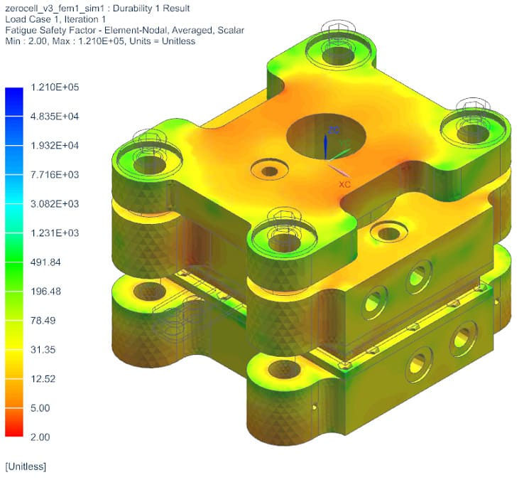
Figure 16 – Safety factor

Figure 17 – Life (infinite)

3 Conclusion
With this project, it was possible to accurately digitally reproduce the PEM fuel cell model, demonstrating the capabilities of Simcenter 3D to integrate with STAR-CCM+ for more complex analyses and obtain physical results consistent with those observed in the real world. In addition, it was possible to ensure that for the conditions tested, the cell has an excellent safety coefficient against fatigue failure. to integrate with STAR-CCM+ for more complex analyses and obtain physical results consistent with those observed in the real world. In addition, it was possible to ensure that for the conditions tested the cell has an excellent safety coefficient against fatigue failure.
STAR-CCM+ and Simcenter 3D Integration allows the fuel cell design to be complete, allowing topological optimizations based on the cell's operating data, in order to guarantee structural resistance and tightness without running the risk of failures. allows the fuel cell design to be complete, allowing topological optimizations based on the cell's operating data, in order to guarantee structural resistance and tightness without running the risk of failures.
Want to know more and in more detail? Schedule a meeting with us now or contact us through one of our means of communication! In the next post we will present the systemic simulation of the integration of the fuel cell in a hybrid vehicle in Amesim, based on the integration of the results obtained in STAR-CCM+ and Simcenter 3D!
WhatsApp: +55 (48) 988144798
E-mail: contato@caexperts.com.br
4 References
BEDNAREK, Tomasz et al. Development of reference hardware for harmonised testing of PEM single cell fuel cells. 2021.
BEDNAREK, Tomasz (2021), “The JRC ZERO∇CELL design documentation”, Mendeley Data, V1, doi: 10.17632/c7bffdv7yb.1
Comments